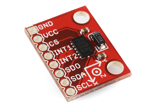
■關於 ADXL345:(摘錄於 ADI 官方網頁)
ADXL345是一款小巧纖薄的低功耗三軸加速度計,可以對高達±16 g的加速度進行高分辨率(13位)測量。數字輸出數據為16位二進制補碼格式,可通過SPI(3線或4線)或者I2C 數字接口訪問。
ADXL345非常適合移動設備應用。它可以在傾斜檢測應用中測量靜態重力加速度,還可以測量運動或衝擊導致的動態加速度。它具有高分辨率(4 mg/LSB),能夠測量約0.25°的傾角變化。使用ADXL345等數字輸出加速度計時,無需進行模數轉換,從而可以節省系統成本和電路板面積。此外,ADXL345內置多種功能。活動/非活動檢測、單擊/雙擊檢測以及自由落體檢測均在內部完成,無需主機處理器執行任何計算。內置32級FIFO存儲緩衝器可以減輕主機處理器的負擔,起到簡化算法和省電的作用。利用內置的活動/非活動檢測功能,將ADXL345用作“運動開關”(無活動時關閉整個系統,檢測到活動時才開啟),系統可以實現進一步省電。
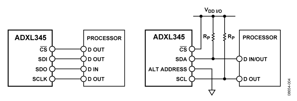
■關於接線:圖左側為 SPI 四線式接線方法(SPI 三線式接線則省略SDO不接),圖右側為 I2C 接線方法(Rp=10K Ohm)。

補充:引腳名稱有很多叫法(或標示)但他們都是相同。
- SDA/SDI/SDIO
- SDO/ALT ADDRESS
- SCL/SCLK
■關於程式:(以下提供 Arduino Code)
程式一:使用 SPI 連接(四線式)(摘錄於:https://www.sparkfun.com/tutorials/240)
//Add the SPI library so we can communicate with the ADXL345 sensor
#include <SPI.h>

//Assign the Chip Select signal to pin 10.
int CS=10;

//This is a list of some of the registers available on the ADXL345.
//To learn more about these and the rest of the registers on the ADXL345, read the datasheet!
char POWER_CTL = 0x2D;	//Power Control Register
char DATA_FORMAT = 0x31;
char DATAX0 = 0x32;	//X-Axis Data 0
char DATAX1 = 0x33;	//X-Axis Data 1
char DATAY0 = 0x34;	//Y-Axis Data 0
char DATAY1 = 0x35;	//Y-Axis Data 1
char DATAZ0 = 0x36;	//Z-Axis Data 0
char DATAZ1 = 0x37;	//Z-Axis Data 1

//This buffer will hold values read from the ADXL345 registers.
char values[10];
//These variables will be used to hold the x,y and z axis accelerometer values.
int x,y,z;

void setup(){
  //Initiate an SPI communication instance.
  SPI.begin();
  //Configure the SPI connection for the ADXL345.
  SPI.setDataMode(SPI_MODE3);
  //Create a serial connection to display the data on the terminal.
  Serial.begin(9600);

  //Set up the Chip Select pin to be an output from the Arduino.
  pinMode(CS, OUTPUT);
  //Before communication starts, the Chip Select pin needs to be set high.
  digitalWrite(CS, HIGH);

  //Put the ADXL345 into +/- 4G range by writing the value 0x01 to the DATA_FORMAT register.
  writeRegister(DATA_FORMAT, 0x01);
  //Put the ADXL345 into Measurement Mode by writing 0x08 to the POWER_CTL register.
  writeRegister(POWER_CTL, 0x08);  //Measurement mode
}

void loop(){
  //Reading 6 bytes of data starting at register DATAX0 will retrieve the x,y and z acceleration values from the ADXL345.
  //The results of the read operation will get stored to the values[] buffer.
  readRegister(DATAX0, 6, values);

  //The ADXL345 gives 10-bit acceleration values, but they are stored as bytes (8-bits). To get the full value, two bytes must be combined for each axis.
  //The X value is stored in values[0] and values[1].
  x = ((int)values[1]<<8)|(int)values[0];
  //The Y value is stored in values[2] and values[3].
  y = ((int)values[3]<<8)|(int)values[2];
  //The Z value is stored in values[4] and values[5].
  z = ((int)values[5]<<8)|(int)values[4];

  //Print the results to the terminal.
  Serial.print(x, DEC);
  Serial.print(',');
  Serial.print(y, DEC);
  Serial.print(',');
  Serial.println(z, DEC);
  delay(10);
}

//This function will write a value to a register on the ADXL345.
//Parameters:
//  char registerAddress - The register to write a value to
//  char value - The value to be written to the specified register.
void writeRegister(char registerAddress, char value){
  //Set Chip Select pin low to signal the beginning of an SPI packet.
  digitalWrite(CS, LOW);
  //Transfer the register address over SPI.
  SPI.transfer(registerAddress);
  //Transfer the desired register value over SPI.
  SPI.transfer(value);
  //Set the Chip Select pin high to signal the end of an SPI packet.
  digitalWrite(CS, HIGH);
}

//This function will read a certain number of registers starting from a specified address and store their values in a buffer.
//Parameters:
//  char registerAddress - The register addresse to start the read sequence from.
//  int numBytes - The number of registers that should be read.
//  char * values - A pointer to a buffer where the results of the operation should be stored.
void readRegister(char registerAddress, int numBytes, char * values){
  //Since we're performing a read operation, the most significant bit of the register address should be set.
  char address = 0x80 | registerAddress;
  //If we're doing a multi-byte read, bit 6 needs to be set as well.
  if(numBytes > 1)address = address | 0x40;

  //Set the Chip select pin low to start an SPI packet.
  digitalWrite(CS, LOW);
  //Transfer the starting register address that needs to be read.
  SPI.transfer(address);
  //Continue to read registers until we've read the number specified, storing the results to the input buffer.
  for(int i=0; i<numBytes; i++){
    values[i] = SPI.transfer(0x00);
  }
  //Set the Chips Select pin high to end the SPI packet.
  digitalWrite(CS, HIGH);
}
程式二:使用 I2C 連接
#include <Wire.h>

int I2C_Address = 0xA7 >> 1;

int X0, X1, Y0, Y1, Z1, Z0;
float X,Y,Z;

void setup(){
    Serial.begin(9600);
    Serial.println("Start : \n");

    Wire.begin();
    setReg(0x2D, 0xA);
}

void loop(){
    X0 = getData(0x32);
    X1 = getData(0x33);
    X = ((X1 << 8)  + X0) / 256.0;

    Y0 = getData(0x34);
    Y1 = getData(0x35);
    Y = ((Y1 << 8)  + Y0) / 256.0;

    Z0 = getData(0x36);
    Z1 = getData(0x37);
    Z = ((Z1 << 8)  + Z0) / 256.0;

    Serial.print("X= ");
    Serial.print(X);
    Serial.print("    Y= ");
    Serial.print(Y);
    Serial.print("    Z= ");
    Serial.println(Z);

    delay(500);
}

/* setReg(reg,data): */
void setReg(int reg, int data){
    Wire.beginTransmission(I2C_Address);
    Wire.write(reg);
    Wire.write(data);
    Wire.endTransmission();
}

/* getData(reg): */
int getData(int reg){
    Wire.beginTransmission(I2C_Address);
    Wire.write(reg);
    Wire.endTransmission();

    Wire.requestFrom(I2C_Address,1);

    if(Wire.available()<=1){
        return Wire.read();
    }
}